A reaction turbine is a type of Steam Turbine that works on the principle that the rotor spins, as the name suggests, from a reaction force rather than an impact or impulse force.
In a reaction turbine there are no nozzles to direct the steam like in the impulse turbine.
The fixed blades, which are the same shape as the moving blades, are mounted to the outer casing where the rotor revolves and are set to guide the steam into the moving blades. Below is a simple diagram of reaction turbine blades:
In the case of reaction turbine, the moving blades of a turbine are shaped in such a way that the steam expands and drops in pressure as it passes through them. As a result of pressure decrease in the moving blade, a reaction force will be produced. This force will make the blades to rotate.
A reaction turbine has rows of fixed blades alternating with rows of moving blades. The steam expands first in the stationary or fixed blades where it gains some velocity as it drops in pressure. Then enters the moving blades where its direction of flow is changed thus producing an impulse force on the moving blades. In addition, however, the steam upon passing through the moving blades, again expands and further drops in pressure giving a reaction force to the blades.
This sequence is repeated as the steam passes through additional rows of fixed and moving blades.
Note that the steam pressure drops across both the fixed and the moving blades while the absolute velocity rises in the fixed blades and drops in the moving blades.
The distinguishing feature of the reaction turbine is the fact that the pressure does drop across the moving blades. In other words, there is a pressure difference between the inlet to the moving blades and the outlet from the moving blades.
Reaction Steam Turbine Shandong Qingneng Power Co., Ltd. , http://www.qnpturbines.com
Specifications
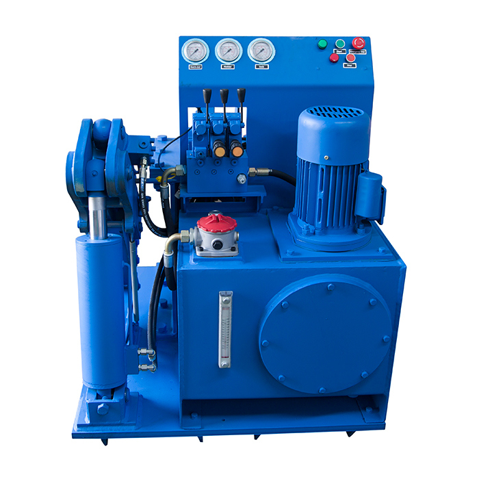
1. For disassembling the dth hammer
2. Easy operation
3. Low cost
4. For 3.5" to 10" hammers
5. Semi-automatic
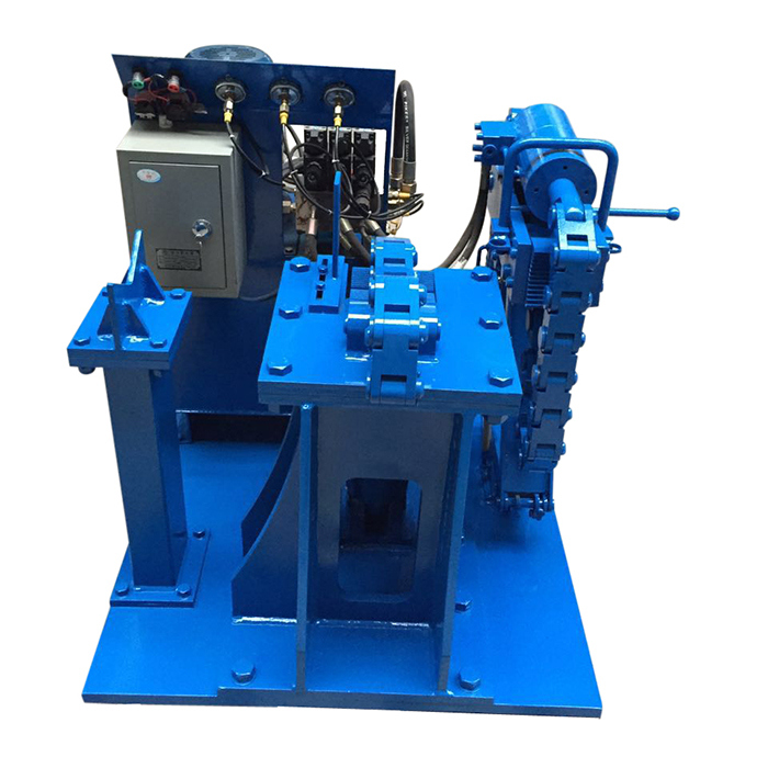
It's a kind of bench to disassemble the dth hammers. The hammers range can be 3" to 10" .
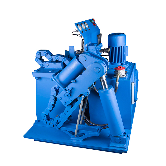
The operation method as below:
1). Put hammer on the bench.
2). Adjust the position of the hammer and wrench; Use wrench to block the top sub side of hammer; Let wrench and jack in the same face.
3). Fix K-shaped base with nut.
4). Fix wrench with nuts.
5). Shake handle of jack slowly till top sub away from hammer.
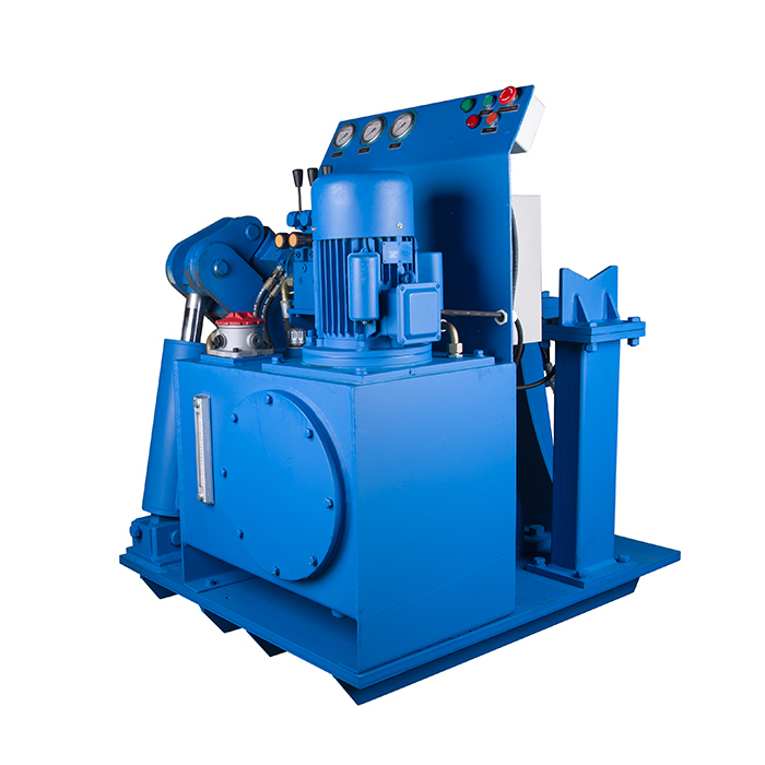
6). After top sub dismantled, grease the jack, release nuts, discharge the K-shaped base and turn around the hammer.
7). Adjust the position of hammer and wrench; Use wrench to block the drive chuck of hammer; Let wrench and jack in the same face.
8). Fix hammer
9). Fix K-shaped base and the wrench with nut.
10). Shake handle of jack slowly till drive chuck away from hammer.
Technical data:
Model
CX-5(manual)
CX-8(manual)
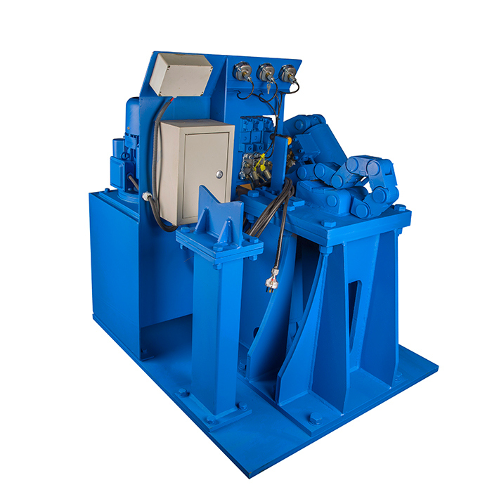
ECX3-8A(electric)
ECX3-8B(electric)
ECX3.5-10(electric)
Operate hammers
3-5"
6-8"
3"-8"
3"-8" (Atlas copco)
3.5-10" (Sandvik)
Length
920mm
1100mm
1900mm
1060
1060
Width
510mm
620mm
900mm
930
1050
Height
875mm
875mm
850mm
1050
930
Weight
200kg
230kg
450kg
800
800
Â
Reaction Turbine Principle:

Reaction Turbine Working:
Special Aspects of Reaction Turbines
Color: Blue
Function: New
Weight: 230kgs
Usage: 3.5"-10"
Brand: Bestlink
Trademark: BESTLINK
Transport Package: Pallet
Specification: steel
Origin: China
HS Code: 82071990
Electric DTH Hammer breakout bench for 3.5-10 inch hammer