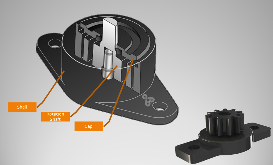
When the digital display machine has a crawling problem, the machine is checked for normality, and the mechanical connection of the speed measuring machine is also checked. Because the speed measuring machine and the motor are generally connected by some mechanical transition pieces, it is also necessary to check the mechanical connection state of the speed measuring machine. Also check the status of the drive system and the status of the motor. For the side of the drive system, the corresponding inspection means should be adopted for different speed control systems. For older transmission systems such as discrete components, the relevant detection point voltage of the system board can be measured, and the speed regulator and the current regulator output voltage circuit can be measured one by one to determine whether there is damage to the integrated circuit components or other power components. Virtual connection and other phenomena. If you have a machine with the same type of system or have related spare parts, you can also replace the corresponding board to find out the faulty component as soon as possible. For systems with high integration, if the system has a touch screen, the status of the system can be monitored through an electronic touch screen, and the corresponding parameters can be changed for testing. It is also possible to change the output state of the system by adjusting the corresponding potentiometer of the system. For the DC speed control system, the proportional gain parameter, the integral time parameter, and the dead zone adjustment potentiometer can be adjusted. Because different systems have certain stability performance at the factory, sometimes the system may work after a period of time, due to the aging of components or due to external environmental factors, the stability of the system may be reduced, so that the output voltage of the system is Fluctuation, through the above adjustments can restore the stability of the system. In addition, the system is regularly cleaned and cleaned, and the system fan is inspected to eliminate short-circuit caused by dust and system instability caused by temperature. For the motor side, if it is a DC motor, measure its armature resistance value, excitation winding resistance value and armature winding inter-turn resistance value, compare with the normal state resistance value, and observe the contact between the motor brush and the armature. If these conditions are not good, the crawling phenomenon may occur. CNC machine tools For CNC machine tools, because there is a numerical control position loop to participate in the control, in addition to considering the above factors, we must also consider the position feedback. The position loop gain bias assembly affects the stability of the system output and may cause creep. However, if the gain is too low, the system following error will be too large. Therefore, the value of the position loop gain value depends on the working state and dynamic characteristics of the machine. If there is signal interference on the feedback line, or the reading head is loose, the dirt on the digital scale and the loose connection of the encoder may cause this malfunction. The easiest way to determine the position loop fault is to shield the position loop from the CNC system, and use the given method to determine whether the position loop is faulty. The approach taken is different for different CNC systems. For older systems such as Siemens 810, 820, 850, 880, etc., the shield plug can be inserted at the position feedback interface, or the coordinate axis can be canceled in the machine data, and the given signal is added with the battery box, if crawling If it is eliminated, it can be determined that the position loop is faulty. For new systems such as 840D and 802D, the coordinate axis can be defined as a virtual axis directly in the machine data, and then given for judgment. In addition, for some position feedback, the feedback signal is weak due to the long distance, so there is a zoom box in the middle, and the state of the magnifying box is not good, which may cause crawling. In addition to the above possible electrical factors, mechanical aspects can also cause creep. For example, the pressure of the static pressure guide rail is not enough, the floating amount of the sliding disc is too low, the oil on the ball screw is lacking, the motor bearing is wrinkled, the lubrication is not good, and the like. There are many possible factors that cause the machine to crawl. This requires us to start from the mechanical and electrical aspects and patiently find the real point of failure until the fault is finally solved. (Finish) Rotary Damper with gear. Gear Damper is used to dampen drives, control speed, and many other applications. Gear dampers are widely used in automobile interior decoration, household electric appliances,etc. Gear damper increasing equipment life and reducing maintenance expenses.
NOTE:
1. Please contact the corresponding product engineer for specific torque products.
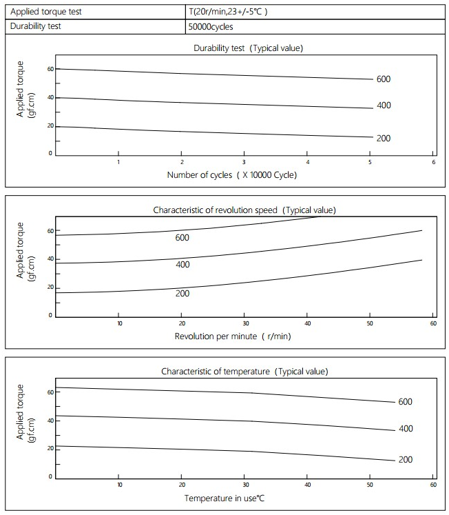
2. Max. rotation speed: 50r/min
3. Max. circle rate: 6 cycle/min(Clockwise360 °, 360 ° anti-clockwise for 1 cycle)
4.Operating temperature: -10~50℃
5.Storage temperature:-30~80℃
Applied torque: (T)
Test Temperature: 23+/-5℃
Rotating speed:20r/min
Durability test Method: Clockwise 360 °, 360 ° anti-clockwise
Rotating speed:20r/min
Test Frequency: 1cycle/min
Test Temperature: 23±5℃
Durability test cycle: 50000cycle
Test result criteria: Store in the room temperature for 24 hours or more after the test, recording to the torque T=T±30%T.
Gear Damper,Hinge Dampers,Plastic Gear Damper,Small Rotary Gear Damper,Decoration Gear Damper Shenzhen ABD Equipment Co., Ltd. , https://www.abddamper.com

