Industrial technology Li Lingchun (Chongqing Public Security Fire Corps Special Service Detachment Chongqing 401121) has occupied a large part. This paper analyzes the current methods of plugging leakage through the introduction of common leakage components, and puts forward constructive opinions. In petrochemical plants, gas storage tanks are used to store chemical gas, which is commonly used to store and transport gas. Because the gas in the storage tank is often flammable, toxic, corrosive, and has a certain pressure, if Improper disposal will result in serious chemical accidents and significant losses. Therefore, how to quickly, effectively and safely dispose of gas storage tank leakage is a topic worthy of discussion in the current chemical disaster disposal. Gas storage tanks can be divided into high-pressure gas storage tanks, low-pressure gas storage tanks and atmospheric pressure gas storage tanks according to the pressures of the gas storage. According to the materials used in the construction of gas storage tanks, stainless steel gas storage tanks can be divided into carbon steel. Stainless steel gas storage tank and alloy material stainless steel gas storage tank. 1 Analysis of the cause of leakage of gas storage tanks. Knowing that you know yourself and know what to do, there is no war in the battle. "Since we have to deal with the leakage of gas storage tanks, we must first understand some basic common sense of the gas storage tank system. Here, we will talk about several leaks of gas storage tanks. Part. 1.1 Valve valve is the component that controls the flow of gas in the gas storage tank system. The operator can change the passage section and the flow direction of the medium through the valve. The valve has diversion, cut-off, regulation, throttling, check, diversion or overflow relief. Features. Usually, the working pressure of the valve is between 0.00131000MPa, the working temperature of the valve is from -2691430C, and the control of the valve is manual, electric, hydraulic, pneumatic, worm gear, electromagnetic, electromagnetic-hydraulic, Electro-hydraulic, gas-hydraulic, spur gear, bevel gear drive, etc. Valves are the most prone to leaks in gas storage systems. According to statistics, more than 50% of leaks come from valves. Among them, valve body leakage, bonnet leakage, leakage at the packing, leakage at the joint of the sealing ring, and falling off of the closing parts are the main reasons for valve leakage. 1.2 Flange flange is mainly used for the connection between gas pipelines, but also for pipe ends. Flanges can be divided into integral flanges, looper flanges and threaded flanges according to structure classification. Flange contact surface roughness is not high, the stiffness is not enough, the sealing surface is scratched, the quality of the gasket is not high, the gasket selection error and other factors are easy to cause the flange to leak, the flange leakage is generally concentrated flange gasket The part of the piece. 1.3 Compressor Compressor is a mechanical sounding used to transport gas to a gas storage tank and increase gas pressure. It is the power system of the whole gas storage tank system. It sucks low-pressure gas from the suction pipe, and after the motor is driven to drive the piston to compress it, it inputs high-pressure gas into the gas storage tank. The compressor is generally composed of a casing, an electric motor, a cylinder block, a piston, and a control sound. When the compressor is in operation, friction between the seal ring and the piston rod easily causes deformation of the seal ring, resulting in gas leakage. 1.4 Pressure relief valve The pressure relief valve can automatically open and close with the pressure change of the gas storage tank system. When the pressure in the gas storage tank or pipeline exceeds the pressure set by the pressure relief valve, the pressure relief valve will automatically open the pressure relief to ensure the sound and The gas pressure in the pipeline is under the set pressure to protect the gas tank from sounds and prevent accidents. According to the principle, the pressure relief valve can be divided into a net weight type pressure relief valve, a lever type pressure relief valve, a spring type pressure relief valve, heavy detachment, lever rust, spring looseness, spool failure, and poor joint connection can cause leakage. 1.5 Welding joints Because the gas storage tank system requires a large number of welding processes during the construction process, the quality of the welding process is directly related to the quality of the gas storage tank system. If the welding process is not in place, improper material matching will directly lead to gas leakage. Therefore, the welding of the object is an important part that should be paid attention to during the leakage disposal process. 2 plugging measures In the case of gas leakage in the gas storage tank system, on the one hand we have to repair the leaked gas storage tank system; on the other hand, we can not affect the normal operation of the gas storage tank system during the disposal process. Here, a cold trap method and a hot trap method are proposed. 2.1 Cold trapping method The cold trapping method is a method of trapping a leaking tank without using an open flame. The cold trapping method mainly includes a riveting trapping method and a modified quick-forming steel trapping method. (1) Riveting and trapping method. The riveting and trapping method mainly uses the prefabricated trapping plate to fit the wall of the gas storage tank through the riveting to achieve the purpose of trapping. In the process of plugging, we first thoroughly remove the rust, oil, dust and other impurities from the leak, temporarily seal the leak with wet cotton cloth or adhesive, and then stick the prefabricated gasket to the leak. Then, press the prefabricated trap plate, the trap plate should be completely fitted with the wall of the gas storage tank at the leaking place, and the wall plate, the gasket and the trap plate of the gas tank should be drilled at the same time with the wind drill, and finally the rivet gun is used for the core riveting to complete the trap. . Non-sparking tools should be used throughout the process and it is strictly forbidden to use electric drills. The riveting and trapping method is gradually replaced by the modified quick-form steel trapping method due to the complicated procedure and poor stability after trapping in the operation process. (2) Modified flash steel trapping method. The modified quick-forming steel trapping method uses a reinforced steel repairing agent, and the repairing agent is cured to achieve the purpose of filling the leak after filling the repairing agent for a certain period of time. The method has the advantages of convenient operation, excellent adhesion and curing. It has the characteristics of high strength, no shrinkage, no rust and long use time. For example, a plasticine-like quick-making steel produced by Pu Shi Company of the United States can cure for only a few minutes and can be used for permanent bonding. It can be used on containers, pipes and some parts of steel, iron, aluminum and other metal materials. Filling and bonding of leaks, cracks, blisters, defects, breaks, damage, etc. In the operation process, the modified quick-release steel trapping method should firstly clean up the impurities such as floating rust, dust and oil collapse in the leaked part, because the cleanliness of the impurity cleaning is directly related to the final plugging effect. Then take out the modified accelerated steel colloid in the plastic tube, cut the required amount, mix the two core materials of the inner core and the outer skin into one color (about 12 min), ensure that the two colloids are evenly mixed, and then firmly compact the adhesive. Fasten to the leak and squeeze into the holes and cracks as much as possible. The mixed adhesive will react quickly. The colloid will start to heat up slightly after 35 minutes. After 1020min, the mixed gel will become very hard, thus achieving plugging. Objective, the modified quick-fill steel trapping method has a good effect especially for trapping some narrow irregular sounds. 2.2 Thermal trapping method The hot trapping method is to use the open flame on the gas storage tank to adopt the welding technology, and strictly follow the welding trapping process. The hot trapping method first cleans the rust, paint, dust and other impurities on both sides of the crack, and then uses the cement to temporarily crack the crack. Sealing, check the air tightness with soapy water to ensure that it has no gas to escape, weld two bolts at the appropriate position perpendicular to the crack direction, and only perform single side spot welding on the bolt so that the operation can be completed. It is easy to knock the bolt without damaging the tank wall. At this time, block the crack at the leak with a blocking plate, tighten the bolt after the pressure plate is covered, and then measure the airtightness with soapy water. If the airtightness is good, the blocking plate can be welded. Finally, the pressure plate and the bolt are removed to complete the plugging. 3 Conclusion In the gas tank leakage disposal, on the one hand, we must strictly follow the formal disposal procedures, but at the same time, we must also consider the pressure, gas properties, danger, geographical characteristics, economy, environmental protection when taking measures. If factors such as sex are neglected, our disposal will be in a passive situation and even have serious consequences. This requires our commanders to have a clear mind, scientific judgment, and decision-making.
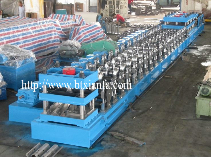
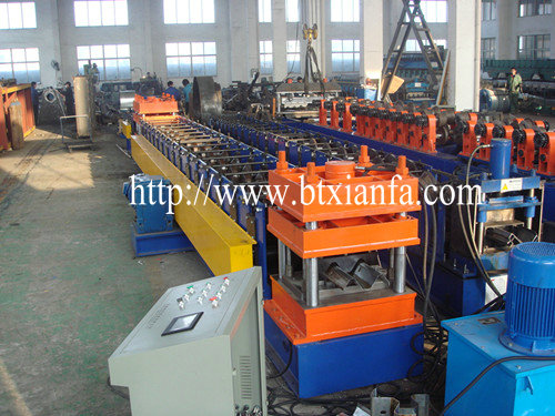
Highway Guardrail Roll Forming Machine, Highway Guardrail Forming Machine, Highway Guardrail Forming Machine for Sale, Expressway Guardrail Roll Forming Machine
· TECHNICAL
SPECIFICATION
(1) 5
tons hydraulic un-coiler:
Hydraulic motor drives. One single-head
structure. It has a pressing arm to prevent the coil loose.
Electric uncoiling, hydraulic motor tenses the
coil inner.
The max. coil inner-diameter is 508mm.
The max. coil outter-diameter is 1200mm.
The max. width of coil is 1250mm.
The max. capacity is 5 tons.
(2)
Roll-Forming M/C:
Welded steel structure base, chains transmit,
motor drives it. The machine include the filming device .
The roller is designed by Germany software
COPRA, and has FEA analysis, which can promise the product precision.
About12 stations to form; Material of Roller: 45#,
with hard chrome coated, polishing,
Voltage:380V/50Hz; Line speed: about 3.5 m/min
(3)
Hydraulic pressing/ Cutting:
Stop to press, Stop to cut, Post cut .Cutting
tool material: Cr12, pressing tool material:40Cr.
Tolerance of the cutting length ±2mm.
(4)
Product Rack
It is 2 parts, 6 meters total.
Un-powered.
(5)
Hydraulic System:
It offers power for the cutter.
(6)
Electrical System:
It uses Siemens PLC system to control the
whole line. It can measure and cut the length automatically. Frequency adjusts
the speed and it has the self-control speed function.
Human-machine screen, touch screen control.
The length can be set in touch screen freely and operation is simple.
The surround connecting wires adopts aviation
socket or fast-speed plug.
(7) Safety barrier system
To protect the workers safely when working.
Highway Guardrail Roll Forming Machine Highway Guardrail Roll Forming Machine, Highway Guardrail Forming Machine, Highway Guardrail Forming Machine for Sale, Expressway Guardrail Roll Forming Machine Botou Xianfa Roll Forming Machine Factory , http://www.rollformingmachinecn.com
